banner
 (
(Overview of the 2nd Generation Intel® Galileo Board
JML Books
 Getting Started with Intel Galileo by Call Number: 004.16 RICISBN: 9781457183089Publication Date: 2014Getting Started with the Intel Galileo gets you up and running with this new, x86-powered board that was developed in collaboration between Arduino and Intel. You'll learn how to set it up, connect it to your computer, and begin programming. You'll learn how to build electronics projects around the Galileo, and you'll explore the features and power that make it different from all the boards that came before.
 30 Arduino Projects for the Evil Genius by Call Number: 006.7 MONISBN: 9780071817721Publication Date: 2013So Many Fiendishly Fun Ways to Use the Latest Arduino Boards Fully updated throughout, this do-it-yourself guide shows you how to program and build fascinating projects with the Arduino Uno and Leonardo boards and the Arduino 1.0 development environment.
 Sylvia's Super-Awesome Project Book by Call Number: 629.8 TODISBN: 9780989151160Publication Date: 2014A book by a kid for kids of all ages! Super-Awesome Sylvia is a kid who loves making, tinkering, and art. Her Web video series, Super-Awesome Sylvia's Super-Awesome Maker Show, has millions of views. In this super fun book, Sylvia teaches you to understand Arduino microcontroller programming by inventing an adjustable strobe and two digital musical instruments you can play! Along the way, you'll learn a lot about electronics, coding, science, and engineering.
 Adventures in Arduino by Call Number: 005.1 STEISBN: 9781118948477Publication Date: 2015Arduino programming for the absolute beginner, with project-based learning Adventures in Arduino is the beginner's guide to Arduino programming, designed specifically for 11-to 15-year olds who want to learn about Arduino, but don't know where to begin. Starting with the most basic concepts, this book coaches you through nine great projects that gradually build your skills as you experiment with electronics.
 Hacking Electronics by Call Number: 621. 38 MONISBN: 9780071802369Publication Date: 2013-04-02Bring your electronic inventions to life! "This full-color book is impressive...there are some really fun projects!" -GeekDad, Wired.com Who needs an electrical engineering degree? This intuitive guide shows how to wire, disassemble, tweak, and re-purpose everyday devices quickly and easily. Packed with full-color illustrations, photos, and diagrams, Hacking Electronics teaches by doing--each topic features fun, easy-to-follow projects. Discover how to hack sensors,accelerometers, remote controllers, ultrasonic rangefinders, motors, stereo equipment, microphones, and FM transmitters.
 Making Things Move by Call Number: 621. 8 ROBISBN: 9780071741675Publication Date: 2010-12-08Get Your Move On! In Making Things Move: DIY Mechanisms for Inventors, Hobbyists, and Artists, you'll learn how to successfully build moving mechanisms through non-technical explanations, examples, and do-it-yourself projects--from kinetic art installations to creative toys to energy-harvesting devices. Photographs, illustrations, screen shots, and images of 3D models are included for each project. This unique resource emphasizes using off-the-shelf components, readily available materials, and accessible fabrication techniques. Simple projects give you hands-on practice applying the skills covered in each chapter, and more complex projects at the end of the book incorporate topics from multiple chapters. Turn your imaginative ideas into reality with help from this practical, inventive guide.


Arduino Tutorials and Projects
- Make: Arduino tutorialsA collection of arduino tutorials and articles from Make magazine.
- Arduino PlaygroundA wiki where all the users of Arduino can contribute and benefit from their collective research. This is the place to post and share your own code, circuit diagrams, tutorials, DIY instructions, tips and tricks, and after all the hard work, to show off your projects!
- Instructables: Arduino tutorialsA collection of arduino tutorials from instructables.
Board Overview
Board Overview
Here’s an overview of the connectors and parts surrounding the Quark processor to form the Galileo board:
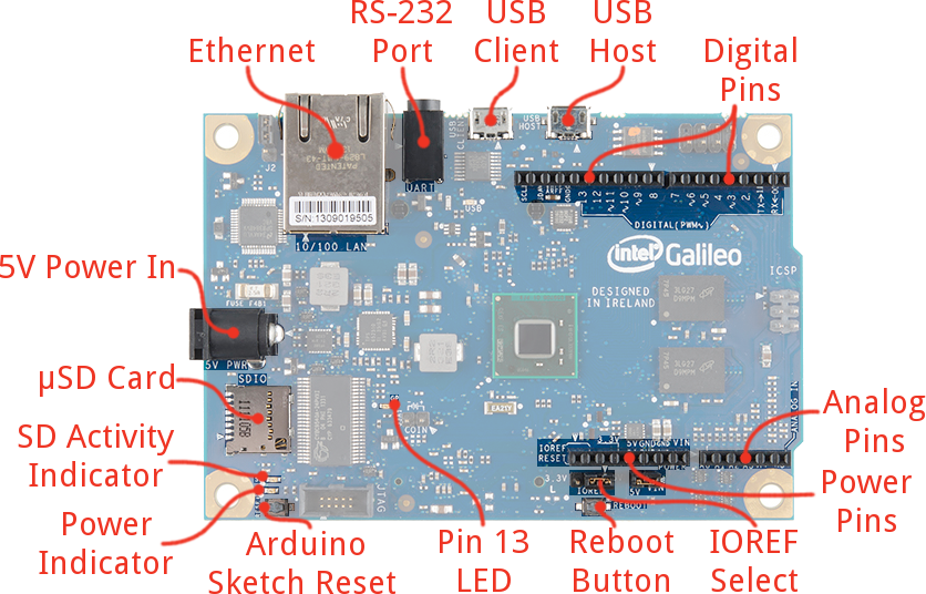
The top side of the Galileo is where the vast majority of the action is, including:
- Ethernet – Connects the Galileo up to any 10/100 Mb/s LAN.
- RS-232 Port – In a weird, 3.5mm “stereo” jack form factor. The sleeve is ground, ring is TX, and tip is RX. With the proper cables, this can be used to access the Linux terminal.
- USB Client – Connect this to your computer to program the Galileo with Arduino.
- USB 2.0 Host – This supports an interface with USB devices like keyboards, mass storage, etc. With a USB hub, up to 128 devices can be connected to this port.
- Standard Arduino connectors:
- 8-pin power header (3.3V, 5V, GND, Reset, etc.)
- 6-pin analog input header (A0-A6)
- 8-pin digital I/O header (D0-D7), which includes UART on pins 0/1, PWM on pins 3, 5, and 6
- 10-pin digital I/O header (D8-SCL), which includes I2C pins and PWM on pins 9, 10, and 11.
- 2x3-pin ICSP header breaks out SPI pins.
- Reboot Button – Pressing this button will reboot the entire Galileo – Linux included. Boot time is about 30 seconds, so don’t press this accidentally!
- Pin 13 LED – As with most Arduinos, the Galileo ties a small, on-board LED to pin 13. Great for the Blink sketch!
- Arduino Reset Button – This will restart solely the Arduino sketch running on the Galileo. This button acts much more like the reset button you may be used to.
- µSD Card – The Galileo supports up to 32GB SD cards. You’ll have to use this socket if you hope to boot the Galileo off the “bigger” Linux image.
- 5V Power In – This is a center-positive, 2.1mm barrel jack for a clean, regulated 5V supply. The power supply should be included with your Galileo.
Flip the Galileo over to find the one highlight on the bottom side of the board: the mini PCIe (Peripheral Component Interconnect Express) socket. This socket is most useful for attaching WiFi cards to give your Galileo easy, wireless network access.
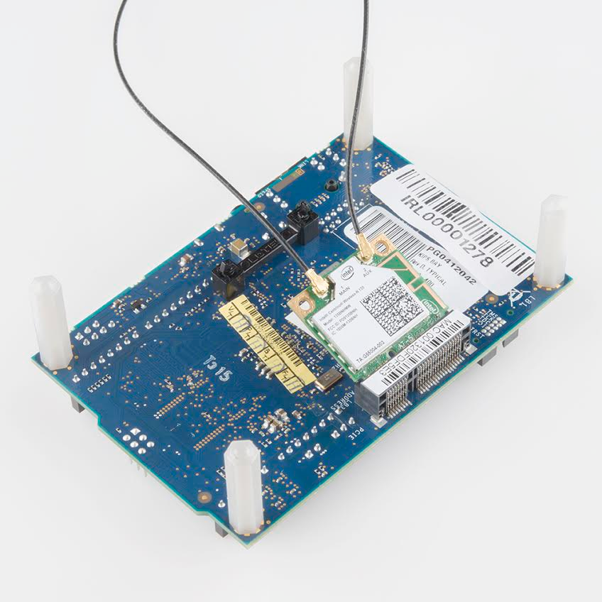
A half-size, mini PCIe WiFi card attached to the mating socket on the bottom side of the Galileo.
Software
Download the Arduino IDE for Galileo
The Arduino Galileo is so wildly different from any other Arduino platform – it’s x86-based, and most commands are sent via the Linux terminal. As such, an entirely re-purposed version of the software is required to upload an Arduino sketch to the board. Click the link below to download the Galileo-ized Arduino IDE:
Download Arduino for Galileo
Make sure you grab the option that matches your operating system – there are versions available for Windows, Mac OS X, and Linux (32 or 64-bit).
The download is about 100MB, and comes as an archived (zip or tgz) file. The next step, “installing”, amounts to unzipping the folder properly.
Install the Arduino IDE for Galileo
Both Mac and Windows versions of the IDE software are delivered in a ZIP format. You’ll need to unzip that archive in order to use the software, but be careful where and how you unzip it!
Mac OS X Install
Mac users should unzip application and move it into your Applications folder. You can rename the application (to differentiate it from any other Arduino installs), but make sure there are no spaces in the name.
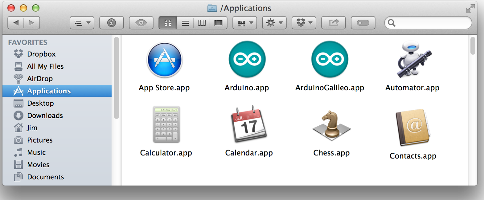
Example Mac directory structure. We’ve renamed the application to ArduinoGalileo to differentiate it from our other Arduino install.
Double-click your newly downloaded Arduino application to run the IDE.
Driver Installation
Once you’ve downloaded and installed the software, the next step is to connect the board and install drivers. This process differs on each operation system, follow the directions below that pertain to your OS:
Mac OS X Driver Install
Mac has built-in driver support for the Galileo, so this setup should be easy. Follow the steps below to install the board on your machine:
- Begin by connecting 5V power to the Galileo.
- Then connect a micro-B USB cable from the USB Client port on the Galileo to an available USB socket on your computer.
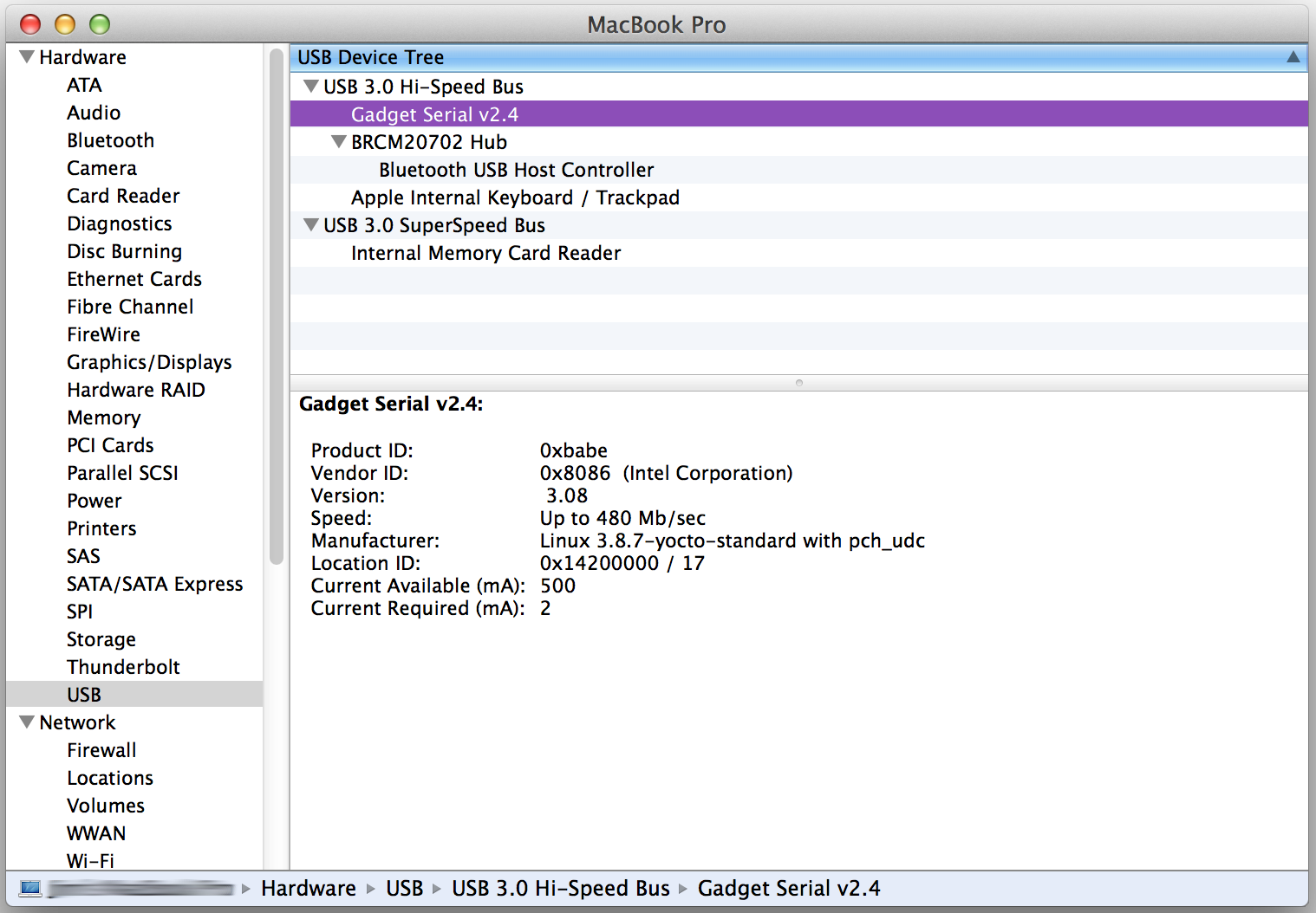
- Wait a few seconds while the Galileo boots up. To verify the Galileo has enumerated properly, open the System Information window (Hold Option > Click the Apple menu in the top left > Click System Information), and check under the USB tab for a Gadget Serial v2.4 entry.
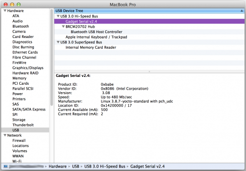
- You can also check under the Network tab to find the Device Name of your Galileo. It should be something like usbmodemXXXX. Keep that name in mind as we go to the next step, updating firmware.
Galileo Getting Started Guide. (2015). Retrieved June 25, 2015, from https://learn.sparkfun.com/tutorials/galileo-getting-started-guide?_ga=1.248714885.3619506.1407391629
Updating Firmware
Updating the Galileo firmware is a good first step to take after driver installation. It helps to prove that your software and drivers are set up correctly, and it prepares your Galileo board with the most up-to-date firmware available. Follow the steps below to update your Galileo board’s firmware.
Step 1: Reboot the Galileo (No SD Cards!)
To reboot the Galileo, first unplug the USB cable. Then unplug the 5V adapter from the board. If there is an SD card in the Galileo, remove it before powering the board back up.
To power the board back up, make sure you plug the 5V cable in first, then plug in a USB cable into the USB Clientport.
Step 2: Set Up the Arduino Galileo IDE
Open up the Galileo-specific Arduino software you downloaded earlier. Mac users can double-click the application file, Windows users should run the Arduino.exe file at the top level of the unzipped folder.
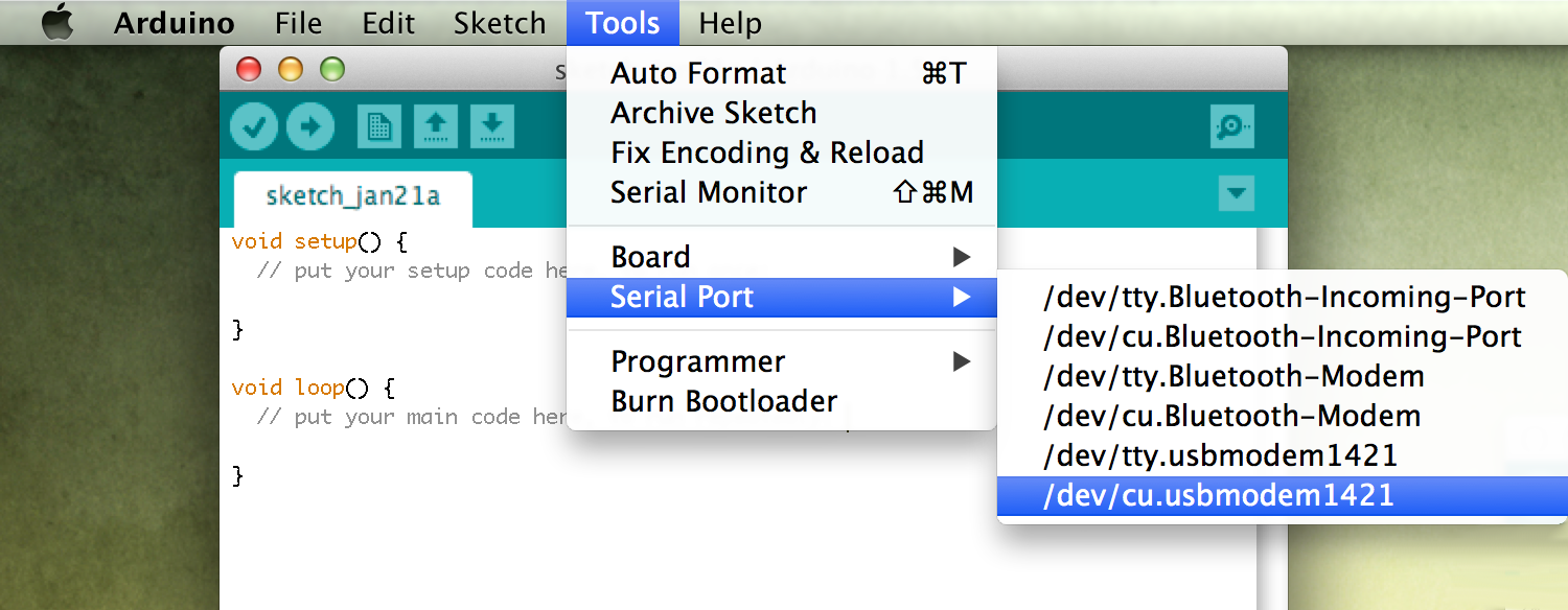
Serial Port Selection
Double-check that the title of the Window has Arduino 1.5.3 at the top. Then the first step is to select the serial port. Go to the Tools menu, then hover over Serial Port. On a Windows machine, select the COM port you saw earlier in the Device Manager. On a Mac machine, select the /dev/cu.usbmodemXXXX (make sure it’s the cu option) that matched what you found in the System Information panel.
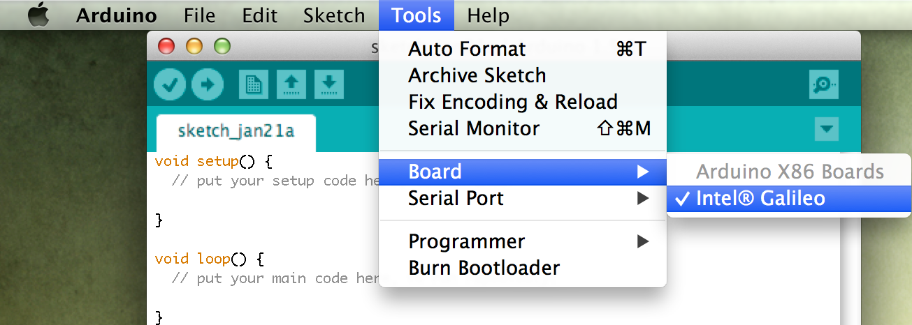
Board Selection
Under the Tools > Board menu, make sure Intel ® Galileo is selected. (Not that you have any other choice.)
Step 3: Firmware Update
Last, but not least, to update the board firmware go to Help > Firmware Update. Then click Yes to proceed.
The software will attempt to communicate with your board, and read the current version of the firmware. On the next window that pops up, select Yes to acknowledge that you’d like to upgrade the firmware, and the process will begin.
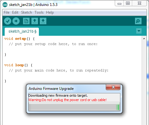
While the progress bar zooms across your screen, make sure you don’t unplug either power or USB from the Galileo. As the pop-up says, the update procedure will take about five minutes. A Target Firmware Upgraded Successfully pop-up will appear after the update completes.
Uploading Blink
As always, the first program to be uploaded to a board is the “Hello, world” of microcontrollers - Blink.
To open the Blink example, go to the File > Examples > 01.Basics > Blink.
/* Blink Turns on an LED on for one second, then off for one second, repeatedly. This example code is in the public domain. */ // Pin 13 has an LED connected on most Arduino boards. // give it a name: int led = 13; // the setup routine runs once when you press reset: void setup() { // initialize the digital pin as an output.pinMode(led, OUTPUT); } // the loop routine runs over and over again forever: void loop() { digitalWrite(led, HIGH); // turn the LED on (HIGH is the voltage level) delay(1000); // wait for a second digitalWrite(led, LOW); // turn the LED off by making the voltage LOW delay(1000); // wait for a second }
Make sure the Serial Port and Board selections are still correct (check the Updating Firmware page for help). Then click the Upload button.
After the upload completes, you should see a tiny, green LED blinking on and off every second. This LED is connected to pin 13 of the Galileo.
Troubleshooting
If you’re having any trouble uploading code, or even updating the firmware, here are a few of the hiccups we encountered, and how we fixed them.
In general, if you’re having any trouble, try rebooting your Galileo (unplug everything, wait a few seconds, plug back in, wait for the boot-up to complete) to see if it fixes it. If that doesn’t work, try rebooting your computer. Sometimes the magic reboot fixes everything.
Improper File Name (Mac)
On Mac, if you get an error like this:
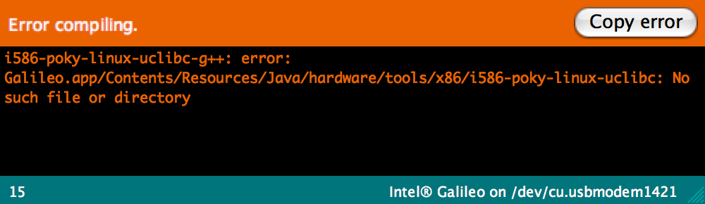
i586-poky-linux-uclibc-g++: error: Galileo.app/Contents/Resources/Java/hardware/tools/x86/i586-poky-linux-uclibc: No such file or directory
There may be a problem with the name of your application. Make sure there are no spaces! For example, if your application is named “Arduino Galileo”, rename it to “ArduinoGalileo”.
Galileo Getting Started Guide. (2015). Retrieved June 25, 2015, from https://learn.sparkfun.com/tutorials/galileo-getting-started-guide?_ga=1.248714885.3619506.1407391629
- Wyliodrin Official WebsiteWyliodrin is a service that allows you to visually create applications for your board and control it directly from the browser.